Welcome to IDI Electronica!!!


Welcome!!! IDI Electronica is a blog for my personal projects and articles to help electronics enthusiasts like me.

Bienvenidos!!! IDI Electronica es un blog con mis proyectos personales y artículos con el fin de ayudar a entusiastas de la electrónica como yo.

Friday, March 20, 2015

Diseño de Circuito con LEDs

Los LED (del acrónimo Diodo Emisor de Luz en inglés) se han convertido uno de los componentes electrónicos más utilizados en el mundo. Los LED son más baratos que otros tipos de fuente de luz, consumen menos poder, producen menos calor, y su tamaño los hace ideales para un sin fin de aplicaciones.


CONCEPTOS BASICOS

1. Los LEDs son semiconductores. La Ley de Ohm (V=iR) todavía aplica, pero tenemos que considerar la caída de voltaje de conducción (Vf por Forward voltage en inglés) del LED cuando hacemos nuestros cálculos.

2. Los LEDs tienen 2 regiones básicas de operación: De conducción (forward region en inglés) y de corte (reverse region en inglés). En la región de conducción, el LED actúa como un conductor. La corriente fluye de sólamente del ánodo al cátodo y el LED se enciende. En la región de corte, el LED se convierte en un aislante y por lo tanto no hay flujo de corriente. También existe la región de ruptura, causada por el exceso de voltaje en sentido opuesto, donde la corriente fluye de cátodo a ánodo. Sin embargo, esta región normalmente daña el LED.

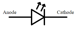
Fig. 1. Símbolo de esquemática de un LED mostrando el ánodo y el cátodo


3. El LED entra en la región de conducción cuando el voltaje de alimentación (Vs por voltage source en inglés) es mayor a la caída de voltaje de conducción del LED (Vf). Este valor se puede encontrar en la datasheet (hoja de detalles técnicos del producto).

4. En LEDs comunes, el cátodo está normalmente marcado por un contacto más corto y por una ranura plana en el cuerpo del LED.

Fig. 2. Dimensiones físicas de un LED


5. El brillo del LED es proporcional al flujo de corriente directa. Demasiada corriente puede dañar o quemar el LED; poca corriente hará que apenas se vea la luz. Como el LED puede funcionar como un conductor, necesitamos colocar una resistencia en serie para controlar el flujo de corriente.

Fig. 3. Circuito simple con un LED 


6. La ecuación para calcular la resistencia del circuito es simple. Tomamos el voltaje de fuente (Vs) y sustraemos el voltaje de conducción (Vf) del LED, luego dividimos ese número por la corriente directa (If) deseada y el resultado nos da la resistencia que necesitamos.


Eq. 1. Ley de Ohm usada para calcular la resistencia de un circuito con LED

7. Idealmente, queremos usar la corriente directa recomendada por el fabricante en la datasheet del LED. Más corriente nos da más brillo, pero también reduce el tiempo de vida del LED.


Diseño de Circuito de LED

Para este ejemplo, utilizamos un LED blanco fabricado por Vishay [Datasheet].

1. Primero, usamos el datasheet para encontrar el voltaje de conducción (Vf) y la corriente directa recomendada (If). Estos valores se encuentran normalmente en la sección Electrical Characteristics del datasheet.


Fig. 4. Fragmento del datasheet de un LED

Para nuestro LED, Vf tiene un rango de 2.8V a 3.6V. Esto, debido a que los LEDs nunca son perfectamente idénticos a la hora de ser fabricados. La única forma de saber el Vf exacto del LED es midiéndolo con un multimetro una vez que el circuito es construído. En este ejemplo, usaremos Vf=3.2V.

Vf = 3.2V
If = 20mA

2. Encontramos la caída de voltaje de alimentación sobre la resistencia y el LED en serie. Para este ejemplo, usamos una batería de 9V.

Vs = 9V

3. Aplicamos nuestros números en la ecuación eq. 1 y el resultado es el valor de la resistencia.

(Vs – Vf) / If = (9V – 3.2V) / 0.020 = 290Ω

Fig. 5. Ejemplo de circuito con LED


Usando Multiples LED en Serie

Si nuestro circuito usa varios LEDs en series, simplemente sumamos los voltajes de conducción (Vf) de cada LED y los agregamos a nuestra ecuación para calcular la resistencia R.

Para este ejemplo, usamos 3 de los LEDs de Vishay en serie y usamos los valores Vs=12V, Vf= 3.2V, y If=20mA.

La ecuación para calcular la resistencia sería:

 (Vs – Vf – Vf – Vf) / If = (12 – 3.2 – 3.2 – 3.2) / 0.020 = 120Ω

Fig. 6. Circuito con múltiples LEDs en serie


Thursday, March 19, 2015

LED Circuit Design

Light emitting diodes (LED) are one of the most commonly used electronic components in today’s world. They are cheaper than other light sources, use much less power, dissipate less heat and their small form factors makes them ideal for countless applications.

BASIC CONCEPTS

1. LEDs are semiconductors. While Ohm's Law (V=iR) still applies, we must consider the voltage drop of the LED (Vf) first when doing the calculations.

2. LEDs have two states or regions of operation: Forward-bias and reverse-bias. In simple terms, forward-bias makes the LED a conductor (current flows, lights up), and reverse-bias makes it an insulator (no current, no light). In the forward-bias region, current will only flow from Anode to Cathode. In reverse-bias, no current flows. There's also the breakdown region, where applying enough voltage in the opposite direction will create a reverse current. Doing this will usually damage the LEDs so we want to avoid it.


Fig. 1. Schematic symbol for LED showing anode and cathode


3. The LED is forward-biased (turned on) when the source voltage (e.g. power supply) is higher than the forward voltage (Vf) of the LED. The forward voltage can be found in the LED's datasheet. 

4. For standard LEDs, the cathode will usually have a shorter pin and the package will have a flat notch on its side.

Fig. 2. Package dimensions of LED


5. LEDs are current-controlled devices; brightness is proportional to the current flow. Too much current will burn them; too little will dim them. Since a forward-biased LED is a conductor, we need to use a resistor in series to control the current flow.

Fig. 3. Simple LED series circuit


6. The equation to calculate the value of the resistor in the LED circuit is simple. We take the voltage source (Vs), we subtract the LEDs forward voltage (Vf) and divide the result by the LEDs forward current (If). The LEDs forward voltage and current are usually found in the LEDs datasheet and will vary depending on the color and type of LED. This equation is simply Ohm's Law.

Eq. 1. Ohm's Law applied to LED resistor calculation

7. Ideally, we will use the forward-current recommended by the manufacturer in the datasheet. Increasing the current will increase the brightness, but may also reduce the LEDs life span. If we exceed the maximum current rated in the datasheet, the LED might get damaged.

Designing a LED Circuit

For this design example, I’ll be using a white LED manufactured by Vishay [Datasheet].

1. First, we use the datasheet to find the forward voltage (Vf) and the typical forward current (If) of the LED. We will find Vf and the typical If in the Electrical Characteristics section.


Fig. 4. Fragment of LEDs datasheet

For this LED, Vf ranges from 2.8V to 3.6V. This occurs because LEDs will never be identical due to manufacturing imperfections. The only way of finding the actual Vf value, is measuring it with a volt-meter once the circuit is built and running. For this example, we’ll use the average of those values, 3.2 volts. The typical forward current is the value used by the manufacturer for testing.

Vf = 3.2V
If = 20mA

2. Find the voltage drop across both the LED and the resistor. In this example, we’ll be using a 9V battery.

Vs = 9V

3-Substitute the values in eq.1 to calculate the resistor value.

(Vs – Vf) / If = (9V – 3.2V) / 0.020 = 290Ω

Fig. 5. LED series circuit example


Using Multiple LED in Series

To use multiple LEDs in series, we simply need to add the forward voltage (Vf) of each LED in the series into the equation.

For this example, we are using 3 of the Vishay LEDs in series and our values are Vs=12V, Vf= 3.2V, and If=20mA.

The equation to calculate our resistor would be:

 (Vs – Vf – Vf – Vf) / If = (12 – 3.2 – 3.2 – 3.2) / 0.020 = 120Ω

Fig. 6. Multiple LED series circuit example