![Imagine, Discover, Invent ... Electronica [IDI]](https://blogger.googleusercontent.com/img/b/R29vZ2xl/AVvXsEgpK8kNefQOnpSUBt7MUvjrC0nJNZYelyXR_Is4Qv19asDvl5jfhVosi5VTYfOiTQJjCWUtfk5Lf6aoNjEXFF-XNm2QdKA7PX-bnbse50sRjfwWsssJH2DE0Jy4RdWkDgrAM-Gx7Ac7dHM/s1600/page+header.png)
Light emitting diodes (LED) are one of the most commonly used
electronic components in today’s world. They are cheaper than other light
sources, use much less power, dissipate less heat and their small form factors
makes them ideal for countless applications.
BASIC CONCEPTS
1. LEDs are semiconductors. While Ohm's Law (V=iR) still applies, we must consider the voltage drop of the LED (Vf) first when doing the calculations.
2. LEDs have two states or regions of operation: Forward-bias and reverse-bias. In simple terms, forward-bias makes the LED a conductor (current flows, lights up), and reverse-bias makes it an insulator (no current, no light). In the forward-bias region, current will only flow from Anode to Cathode. In reverse-bias, no current flows. There's also the breakdown region, where applying enough voltage in the opposite direction will create a reverse current. Doing this will usually damage the LEDs so we want to avoid it.
2. LEDs have two states or regions of operation: Forward-bias and reverse-bias. In simple terms, forward-bias makes the LED a conductor (current flows, lights up), and reverse-bias makes it an insulator (no current, no light). In the forward-bias region, current will only flow from Anode to Cathode. In reverse-bias, no current flows. There's also the breakdown region, where applying enough voltage in the opposite direction will create a reverse current. Doing this will usually damage the LEDs so we want to avoid it.
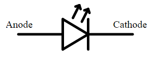
Fig. 1. Schematic symbol for LED showing anode and cathode
3. The LED is forward-biased (turned on) when the source voltage (e.g. power supply) is higher than the forward voltage (Vf) of the LED. The forward voltage can be found in the LED's datasheet.
4. For standard LEDs, the cathode will usually have a shorter pin and the package will have a flat notch on its side.

Fig. 2. Package dimensions of LED

Fig. 3. Simple LED series circuit
6. The equation to calculate the value of the resistor in the
LED circuit is simple. We take the voltage source (Vs), we subtract the LEDs
forward voltage (Vf) and divide the result by the LEDs forward current (If). The
LEDs forward voltage and current are usually found in the LEDs datasheet and
will vary depending on the color and type of LED. This equation is simply Ohm's Law.

Eq. 1. Ohm's Law applied to LED resistor calculation
7. Ideally, we will use the forward-current recommended by the manufacturer in the datasheet. Increasing the current will increase the brightness, but may also reduce the LEDs life span. If we exceed the maximum current rated in the datasheet, the LED might get damaged.
Designing a LED Circuit
For this design example, I’ll be using a white LED
manufactured by Vishay [Datasheet].
1. First, we use the datasheet to find the forward voltage
(Vf) and the typical forward current (If) of the LED. We will find Vf and the
typical If in the Electrical Characteristics section.

Fig. 4. Fragment of LEDs datasheet
For this LED, Vf ranges from 2.8V to 3.6V. This occurs
because LEDs will never be identical due to manufacturing imperfections. The
only way of finding the actual Vf value, is measuring it with a volt-meter once
the circuit is built and running. For this example, we’ll use the average of those
values, 3.2 volts. The typical forward current is the value used by the
manufacturer for testing.
Vf = 3.2V
If = 20mA
2. Find the voltage drop across both the LED and the
resistor. In this example, we’ll be using a 9V battery.
Vs = 9V
3-Substitute the values in eq.1 to calculate the resistor value.
(Vs – Vf) / If = (9V – 3.2V) / 0.020 = 290Ω

Using Multiple LED in Series
To use multiple LEDs in series, we simply need to add the
forward voltage (Vf) of each LED in the series into the equation.
For this example, we are using 3 of the Vishay LEDs in series
and our values are Vs=12V, Vf= 3.2V, and If=20mA.
The equation to calculate our resistor would be:
(Vs – Vf – Vf – Vf) /
If = (12 – 3.2 – 3.2 – 3.2) / 0.020 = 120Ω

Fig. 6. Multiple LED series circuit example
No comments:
Post a Comment